Applet을 실행할 수 없는 경우에는 Java Run-time Environment(JRE)을 설치하십시오. http://java.com/download/
보안설정으로 차단된 응용프로그램과 같은 문제가 발생할 경우에는 Java 제어판의 보안 레벨 설정을 참조하시기 바랍니다.
예외사항 사이트에 https://www.cheric.org를 추가한 후 브라우저를 모두 닫고 다시 시작하면 Applet을 사용하실 수 있습니다.
PROCESS CONTROL APPLET SERIES III
Basics of Control Valve, Instrumentation and Valve Selection
Control Valve as an Actuator in Control System
A Control Valve is a power-operated device used to modify the fluid flow rate in a process system. Thus, it can be used to control liquid, slurry or gas flow rates and pressure of a vessel. Of course, if the fluid is a heating or cooling medium in a jacketed or coiled vessel, the temperature of the vessel can be controlled. The most popularly used power sources are pneumatic and electric power. Since the control valves are supposed to control diverse process variables, it can be very dangerous if control valves do not work as they suppose to. In case of power failure, the control valves should have the right fail position in the event of a loss of signal or power. The most popular power for control valves is the air pressure. In this case, the valve is operated based on the power balance between the air pressure and spring divided by diaphragm. About 20 psia of dehydrated air source are fed to the I/P (Current-Pressure) transducer and a commanding signal which will decide what should be the valve opening is added to I/P transducer. The I/P transducer takes 4-20mA commanding signal and converts to 3-15 psia pneumatic signal. Depending on the type of valve, the 3psia signal corresponds to fully-closed or fully-open position. The flow rates for different valve opening will vary depending on the type of valve plugs. The pneumatic valves are cost-effective and fast in stroking speed but have large size and limited ouput capability. The electric motor powered valves are usually used for high output flow rates with compactness but they suffer from high cost, lack of fail-safe action, slow stroking speed, and etc. The fail-safe mode should be decided based on the process safety. Safety concerns and process requirements will mandate the fail mode of the valve. As a simple example, when a vessel pressure is controlled by adjusting the effluent flow rate with a control valve, the fail mode of the control valve in case of power loss should be fail open to prevent the build-up of vessel pressure. In most applications (about 80%), it is desirable for valves to fail closed.
Objectives of This Applet
This applet is designed to illustrate the followings :
- - Instrumentation for control valve
- - Selection of valve size and valve plug
- - Fail-safe mode of control valve
- - Inherent and installed characteristics
- - Hysteresis and Valve positioner
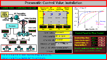
This applet consists of 7 parts. The horizontal thin panels on top and bottom are the title panel and status panel, respectively. The title panel is permanent one and the status panel is changing depending on the situation to give the explanation to users. In the Middle, there are five panels. The leftmost panel shows the process and instrumentation. The middle panel shows the levels of signals for each variable and selections of system options. The rightmost panel shows the graph of valve opening vs. actual flow and control panel for system parameters. In this help, only the panels with special functions will be described.
Process Panel
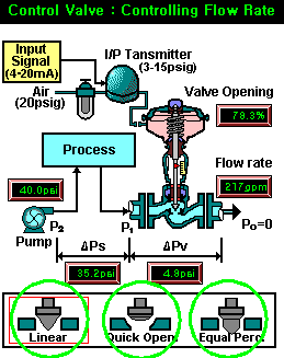
This panel shows the connections of the elements in the implementation relavant to the control valve. The pressures of the system, valve opening and actual flow are displayed in the digital gauges. On the bottom of the figure there are three types of valve plug are displayed. The different valve plug can be selected by clicking the area of interest
Display and Option Panel
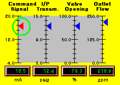
This panel displays the signals that are required to manipulate the control valve. The command signal can be adjusted by dragging the red triangle indicator from 4-20mA.
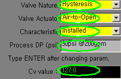
In this panel, several options can be selected. First, the simulated hysteresis of a valve or valve positioner to eliminate the hysteresis can be selected. Then the types of valve plug can be selected among three types. Also, the process delta P can be selected as constant or proportional to square of the flow rate. If the latter option is selected, the control valve will exhibit the installed characteristics. The last input field will change accordingly depending on which parameter is chosen to be entered. After typing the value in, the 'Enter' key should be typed to reflect the change.
In general, control valves have hysteresis which is mainly caused by the sticking of the stem with seal. If the valve nature is selected as 'hysteresis', the valve will not start opening/closing until the command signal changes more than small amount. To prevent this hysteresis, valve positioner can be used and if this option is selected, the valve will operates directly based on the command signal.
Valve actuator can be chosen between 'Air-to-open' and 'Air-to-close'. If 'Air-to-open' is selected, the valve will open more as the command signal increases and vice versa.
The actual flow through the control valve becomes different whether it is installed with process or not. Either 'installed' or 'inherent' characteristics can be chosen.
The process delta P can be specified as pressure drop (psi) at certain flow rate (gpm). Then the pressure drop of the process will be proprtional to square of the flow rate. The format is fixed as '###psi @###gpm'. After type in desired value, press 'ENTER' key to reflect the change into the applet.
Graph and Control Panel
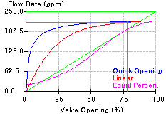
This graph shows the valve opening versus actual flow rate through the control valve in gray color. The graph shows the lines of three types of valve plug. Depending on the types of the valve plug, the paths of changing flow rate are drawn in different colors.
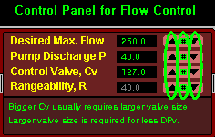
In this panel, the parameters of the control valve system can be adjusted. The parameters can be increased or decreased by a predefined amount by pressing triangles. If the green # key in the middle is pressed an arbitrary number can be typed in the text field of the option panel. If you start typing in the input field the background color will change to red. After type the desired value, press 'ENTER' to reflect the change to the applet. Then, the background color will come back to black and the corresponding parameter value will be updated.
Explain the concept of control valve implementation (Java Applet will help you interactively.)
What is control valve?
What is control valve?
A Control Valve is a power-operated device used to modify the fluid flow rate in a process system. Thus, it can be used to control liquid, slurry or gas flow rates and pressure of a vessel. Of course, if the fluid is a heating or cooling medium in a jacketed or coiled vessel, the temperature of the vessel can be controlled. The most popularly used power sources are pneumatic and electric power. Since the control valves are supposed to control diverse process variables, it can be very dangerous if control valves do not work as they suppose to. In case of power failure, the control valves should have the right fail position in the event of a loss of signal or power.
The power and command signal for control valves
What is control valve?
The most popular power for control valves is the air pressure. In this case, the valve is operated based on the power balance between the air pressure and spring divided by diaphragm. About 20 psia of dehydrated air source are fed to the I/P (Current-Pressure) transducer and a commanding signal which will decide what should be the valve opening is added to I/P transducer. The I/P transducer takes 4-20mA commanding signal and converts to 3-15 psia pneumatic signal. Depending on the type of valve, the 3psia signal corresponds to fully-closed or fully-open position. The flow rates for different valve opening will vary depending on the type of valve plugs. The pneumatic valves are cost-effective and fast in stroking speed but have large size and limited ouput capability. The electric motor powered valves are usually used for high output flow rates with compactness but they suffer from high cost, lack of fail-safe action, slow stroking speed, and etc.
Fail-safe Mode
What is control valve?
The fail-safe mode should be decided based on the process safety. Safety concerns and process requirements will mandate the fail mode of the valve. As a simple example, when a vessel pressure is controlled by adjusting the effluent flow rate with a control valve, the fail mode of the control valve in case of power loss should be fail open to prevent the build-up of vessel pressure. In most applications (about 80%), it is desirable for valves to fail closed.
ATO-FC (Air To Open- Fail Closed) : If a valve has fail closed mode and the valve opens as the air pressure increases.
ATC-FO (Air To Closed- Fail Open) : If a valve has fail open mode and the valve closes as the air pressure increases.
Classification of control valves.
Actuator
Most control valves are operated by a linear-position actuator or some modification of such an actuator. These actuators linearly adjust the distance between the valve plug and valve seat depending on the signal. (globe-style, and gate valves) Other type of actuator is rotary motion actuator. These actuators rotate the plugs, plates or balls in order to adjust the valve opening. (butterfly, ball, and eccentric plug valves)
Valve Body
Control valve bodies may be screwed, flaged, or welded into the flow line. The typical single-ported valves can handle the through flow and angle flow. The typical double-ported valves can handle the through flow, blending and splitting flows.
Valve Plug
The plug and seat geometry is the most significant single factor in determining the flow rate stem position characteristics of the valve. The most popular valve types of different plugs are linear, equal percentage, and quick opening valves depending on the shape of the plugs.
Inherent Flow Characteristics of Control Valves
Valve Coefficient or Valve sizing Coefficient (Cv)
The relationship between valve flow output and valve travel is known as the flow characteristic of the valve. When the flow characteristics are obtained with constant pressure drop across the valve (generally referenced to the standard condition of a constant pressure drop of 6.9kPa or 1lbf/sq.in.), they are called inherent flow characteristics. Three types of them can be seen in the applet when it is initialized. The sensitivity of the rate of change of flow to the valve step position (dQ/dL) at a constant pressure drop is called the valve coefficient, Cv.
The quick-opening : it provides large changes in flow (Q) for very small changes in lift (L). It usually has too high a valve gain for use in modulating control. So it is limited to on-off service, such as sequential operation in either batch or semi-continuous processes. In this case, Cv will decrease as Q increases.
Q = Cv*SQRT(L*DP/gc) (where DP is pressure drop across the valve.)The majority of control applications are valves with linear, equal-percentage, or modified-flow characteristics.
Linear : flow capacity increases linearly with valve travel. For linear valves, the Cv is constant through the whole range.
Q = Cv*L*SQRT(DP/gc)Equal percentage : flow capacity increases exponentially with valve trim travel; equal increments of valve travel produce equal percentage changes in the existing Cv. For equal-percentage valves, the Cv will increase as Q increases.
Q = Cv*RL-1*SQRT(DP/gc) (where R is rangeability.)A modified parabolic characteristic - approximately midway between linear and equal-percentage characteristics. It provides fine throttling at low flow capacity and approximately linear characteristics at higher flow capacity
Rangability (R)
R = (maximum controllable flow)/(minimum controllable flow)
The "rangeability" factor defines a valve's capability to control small flows. The higher the number, the better. On typical small globe valves (1/2") the rangeability is 5:1, and on a large valve (2") it is 75:1.
Turn Down (T)
T = (normal maximum flow)/(minimum controllable flow)
Genrally, valves are sized so that T is around 0.7R where R lies, depending on the type of valve, typically between 20 and 50. For example, if the design of a tank-level control system calls for 25:1 change in inlet flow rate to maintain the level because of a chaging outlet flow rate, then the indicated control valve turndown ratio is at least 25 and the rangeability ratio at least 35.
Installed Flow Characteristics of Control Valves
Installed Flow Characteristic
When valves are installed with a pump, pipes, fittings, and other process equipment, the pressure drop across the valve will vary as the plug moves through its travel. When the actual flow in a system is plotted against valve opening, the curve is called the installed flow characteristic.
Pump Characteristic Curve
Depending on the type of pump, the actual pump discharge pressure may vary.As flow rate increases, the pump discharge pressure is usually decreased and the information on this can be obtained from the vendor of each pump.
In this applet, it is assumed that the pump discharge pressure is constant no matter what the flow rate is.
Linearity of the installed flow characteristics
For the inherent characteristics, the linear valve shows the linear relationship between the flow rates and the valve opening. However, if all the components of the flow control system are installed and the process has pressure drop which is squarely proportional to the flow rate (reasonable assumption for most cases), the equal percentage valves tend to exhibit linear characteistic when the control valves are suitably sized.
Selection of Control Valves
Why is the valve sizing important?
Better valve control prevents "hunting" of the control loop in which the system is constantly adjusting itself to maintain set point. When the operating conditions of the actuator are improved and the full operating range is used, system life span is increased, energy consumption is reduced. For example, a valve with large flow coefficient (Cv) in relation to its size results poor flow characteristic. This means that the valve will supply the required flow when it is only slightly open, thereby utilizing just a small portion of its operating range. Stable control is difficult to achieve because a slight change in valve position results in a disproportionately large change in the heating or cooling output of the controlled device. Energy consumption is increased, people are less comfortable, and life span of valves and actuators is shortened because they never come to rest.
Also, cavitation occurs when vapor bubbles form and implode in a liquid due to an increase then decrease in pressure as liquid flows through a restriction. The imploding vapor bubbles erode the surrounding material and cause an intense noise. Like globe valves, no cavitation should occur if the valve is sized properly.
How to Select Control Valve
Glove valves are commonly used for flow control. But ball valves can be used where accurate control was not important from a cost standpoint. If the pump characteristic (discharge pressure vs. flow rate) is fairly flat and system frictional losses are quite small over the entire operating region, choose a linear valve. However, this situation occurs infrequently because it results from an overdesigned process (pump and piping capacity too large). [Seborg et al.] Otherwise, select a equal-percentage valve or its modification.
The flow rate through a control valve can be adjusted by changing the pressure drop across the valve. And the pressure drop can be changed by adjusting the valve opening. If the control valve takes most of pressure drop in the flow control system, then the control valve can have maximum influence over the process changes and a small size of valve can be used. However, the most economical operating conditions will be found where the the pumping cost is minimal. Thus, the optimum choice would be that the valve takes one-quater to one-third of total pressure drop at the design flow rate.
To select a valve first determine Cv using desired flow rate in gallons per minute (GPM) and pressure drop across the control valve (Delta P):Cv=GPM/Sqrt(Delta P/gc)
Once the Cv value (required Cv) is decided, Depending on the control objective of the flow control system, the rated Cv has to be decided based on the required Cv. If the system requires wide range of operating condition, it is recommended that the control valve be half open at nominal operating condition for controllability. If the system operates on a very small range of operating condition, it is recommended that the required Cv not exceeding 90% of the valve's rated Cv. With the rated Cv, the valve size can be determined from the manufacturer's data books. When the connecting pipe diameter is equal to valve diameter there is no reduction in pipe size and better overall cost for an installed valve. Then examine the linearity between the flow rate and valve opening in the operating region of interest. If it is not suitably linear, adjust the rated Cv and repeat.
Hysteresis of Control Valve and Remedy
Hysteresis of Control Valve
The hysteresys of control valve is a phenomenon that shows different flow rates even at the same valve opening depending on the moving direction of a valve stem. It usually caused by the sticking between the valve stem and the control valve packing. Other causes are loose linkage, pressure drop, etc. The control valve packing is a sealing system which normally consists of a deformable material such as TFE, graphite, asbestos, Kalrez, etc. Usually the material is in the form of solid or split rings contained in a packing box. Packing material is compressed to provide an effective pressure seal between the fluid in the valve body and the outside atmosphere.
Valve Positioner
A valve Positioner is a device used to increase or decrease the air pressure operating the actuator until the valve stem reaches the position called for by the instrument controller. Positioners are generally mounted on the side or top of the actuator. They are connected mechanically to the valve stem so that stem position can be compared with the position dictated by the controller. A positioner is a type of air relay which is used between the controller output and the valve diaphragm. The positioner acts to overcome hysteresis, packing box friction, and valve plug unbalance due to pressure drop. It assures exact positioning of the valve stem in accordance with the controller output.
In this applet, the hysteresis is simulated as a dead band for simplicity. This means that if a small change of commanding signal is applied, the stem sticks and the flow rate will not change. Only if more than certain amount of signal change is applied, the flow rate will change accordingly.
